MEC Standard Configurations
MEC standard configurations are based on an optical laser beam delivery platform, a standard target mounting scheme, and a fixed set of diagnostics adjustable with a narrow range of parameters. Additional standard elements may be permitted at the discretion of the instrument lead if they don't conflict with the designated set. This permission must be explicit for a proposal to be considered as standard configuration at the time of PRP consideration.
MEC is designating two Standard Configurations for Run 27: (1) Uniaxial drive dynamic compression with X-ray diffraction, and (2) side-drive dynamic compression with direct imaging. Details are provided in the tabs below.
X-Ray Diffraction With Uniaxial Compression
This configuration of MEC supports diffraction measurements on targets shocked to pressures up to several Mbar, with shocks propagating along the X-ray direction, using the standard collinear beam delivery. Four ePix10k detectors measure diffraction, with angular range optimized for liquid diffraction at high photon energies (>15 keV). A dual line VISAR diagnostic measures shock break-out to determine pressure. Backward X-ray Thomson scattering (BXRTS) is available at 125° scattering angle.

The lasers hit the sample at an angle of 20° from each side of the x-ray axis. The angle between the target normal and the LCLS x-ray axis is 0° (so that each drive beam is incident at 20°). VISAR is collected normal to the back of the target. 4 Quad detectors are arranged to spatially resolve wide angle scattering from 8 to 72º. BXRTS will be located around 125 degree.

The XRD detection is performed using 4 “quad” cameras from the SLAC ePix10k family. The sensors on each quad are ¼ of a full ePix10k-2M. The MEC variety use twice the standard thickness of Si, 1 mm, to achieve higher quantum efficiency at high photon energies, and are packaged to be robust against EMP from laser-target interaction. The pixel size is 100 µm x 100 µm. Added during Run 18, these detectors have better noise and higher dynamic range than the previous CSPADs, for a similar detector area. For diffraction experiments, the detectors are oriented around the primary interaction point in a Debye-Scherrer transmission geometry, with their positions in the standard configuration illustrated in Figure 3. Here four Quads, labeled as Q0, Q1, Q2 and Q3, are used to record the diffraction signal. The top two quads, Q0 and Q1 access the lowest angles from above the horizontal plane, while Q2 and Q3 are oriented for wider angles in the horizontal plane. Since Run 18, the standard X-ray polarization has been vertical, meaning that lower scattering signal is seen further away from the horizontal plane. The overall coverage in (φ, 2θ) is illustrated in Figure 4.


FXRTS variant
An available variant of the coaxial standard configuration removes quad 2 in favor of a spectrometer in the forward direction for X-ray Thomson Scattering.

Diffraction Analysis
Dioptas is a popular tool for reconstructing diffraction patterns. Access to Dioptas and the psana analysis machines is now brokered through the SLAC Shared Science Computing Facility (S3DF), under which computing resources for SLAC are centralized.
Optical Laser Parameters and Geometry
The full frequency-doubled energy of the long pulse laser is delivered to the target with angles of ± 20 deg. in the horizontal plane relative to the X-rays, with the target oriented normal to the X-rays. Both beamlines can be used simultaneously (7 minutes between shots), or staggered (one shot every 3.5 minutes). The 72 mm beams are focused using 250 mm focal length aspheric lenses (F/3.5), and the focal plane of each beam relative to the target can be adjusted from best focus to ~350 µm out of focus. MEC uses continuous distributed phase plates (CPP) generating circular focal spots of 150, 300 and 600 micron. Phase plates can be manually exchanged during a standard configuration run, requiring a chamber vent. Note that desired pulse shapes and phase plates must be submitted at least 2 months before beamtime.
Targets
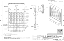
The user provided targets will need to be mounted on target frames that are compatible with the MEC target holder. Please contact an instrument scientist for more information about target mounting. An example target mount design is illustrated in Figure 6.
Parameter table
To be considered for scheduling in this standard configuration, users will be required to include a table in the proposal that lists the specific experimental parameters to ensure compatibility with these configurations. If the experimental parameters are not compatible with the standard configuration or if the table of parameters is incomplete, the proposal will be reviewed and considered for scheduling as a general user proposal. Please see the table of required parameters of the MEC Standard Configuration #1. No fundamental changes to the standard configurations will occur, but some details of the configuration may be updated in response to inquiries, so users should recheck the website before submitting your proposal to confirm that you have the latest information. Address any questions to the instrument staff.
X-ray Imaging With LPL Side Irradiation
This configuration supports direct X-ray Imaging measurements on targets shocked to pressures up to several Mbar, with shocks propagating perpendicular to the X-ray direction. The new MEC X-ray Imager (MXI), located downstream of the target, images the transmitted beam to an X-ray microscope ~4.5 m from TCC. The layout within the chamber is shown in Figures 1 and 2. Diffraction signal can be registered on the ePix10k Quad placed in the Q3 position, described in Configuration 1, covering roughly 22 to 62 degrees (this can be shifted to lower angles by several degrees for the beam time on request). VISAR is also provided to measure shock velocity.


Direct imaging with a coherent beam
The MXI places a stack of 25 to 100 beryllium compound refractive lenses with a front lens distance that can be placed in a range from 97 to 984 mm, with motorized travel in this range of 500 mm and the ability to switch between up to three different lens stacks. The imaging platform is set at a distance of roughly 4.2 m beyond the target. Standard detection consists of a YAG screen imaged by an Optique Peter microscope having magnification options of 2x, 4x and 10x onto an Andor NEO camera.
The beam's high spatial coherence and the imperfect imaging of a Be CRL stack mean that some diffraction effects will be seen even when the sharpest images are formed at target. This allows features such as shock fronts to stand out without large areal density differences. Analysis of the phase contrast aspect is still an active area of investigation.
Please reach out to an MEC point of contact for details on what can be achieved with the imaging platform.
Optical Laser Parameters and Geometry
The full frequency-doubled energy of the long pulse laser is delivered to the target with angles of ± 20 deg. in the horizontal plane relative to the target normal, which has an angle of 90 deg. relative to the X-rays. Shot rate is 7 minutes per shot for full energy using all beams. By operating only two amplification arms at a time and alternating, the rate can be doubled to 3.5 minutes, albeit with roughly half the energy and with some loss in pulse shape quality. The 72 mm beams are focused using 250 mm focal length aspheric lenses (F/3.5), and the focal plane of each beam relative to the target can be adjusted from best focus to a ~100 µm spot. MEC uses phase plates generating circular focal spots of 150, 300 and 600 micron by CPP. Phase plates can be manually exchanged during a standard configuration run, requiring a chamber vent.
Single ePix10k Quad for Diffraction
From configuration #1, Q3 is retained for a reduced range of diffraction, with other quads being incompatible with the imaging and drive laser hardware. Typically diffraction and imaging are taken on different shots since the focusing conditions at target are different. Q3 is also positioned at a smaller angle to avoid interference with the VISAR.

Target Pillars
A stair-step target mount design allows for laser and VISAR access to a target for side-on X-ray imaging of the target. A pillar design is used to mount columns of targets in this way, as shown below:

Parameter table
MEC Instrument Scientist Staff
Eric Galtier, Bob Nagler, Hae Ja Lee, Philip Heimann, Dimitri Khaghani, Gilliss Dyer
Laser Contact
Nick Czapla, Marc Welch