MeV-UED Schematics

SSUED Schematic Labeled.PNG

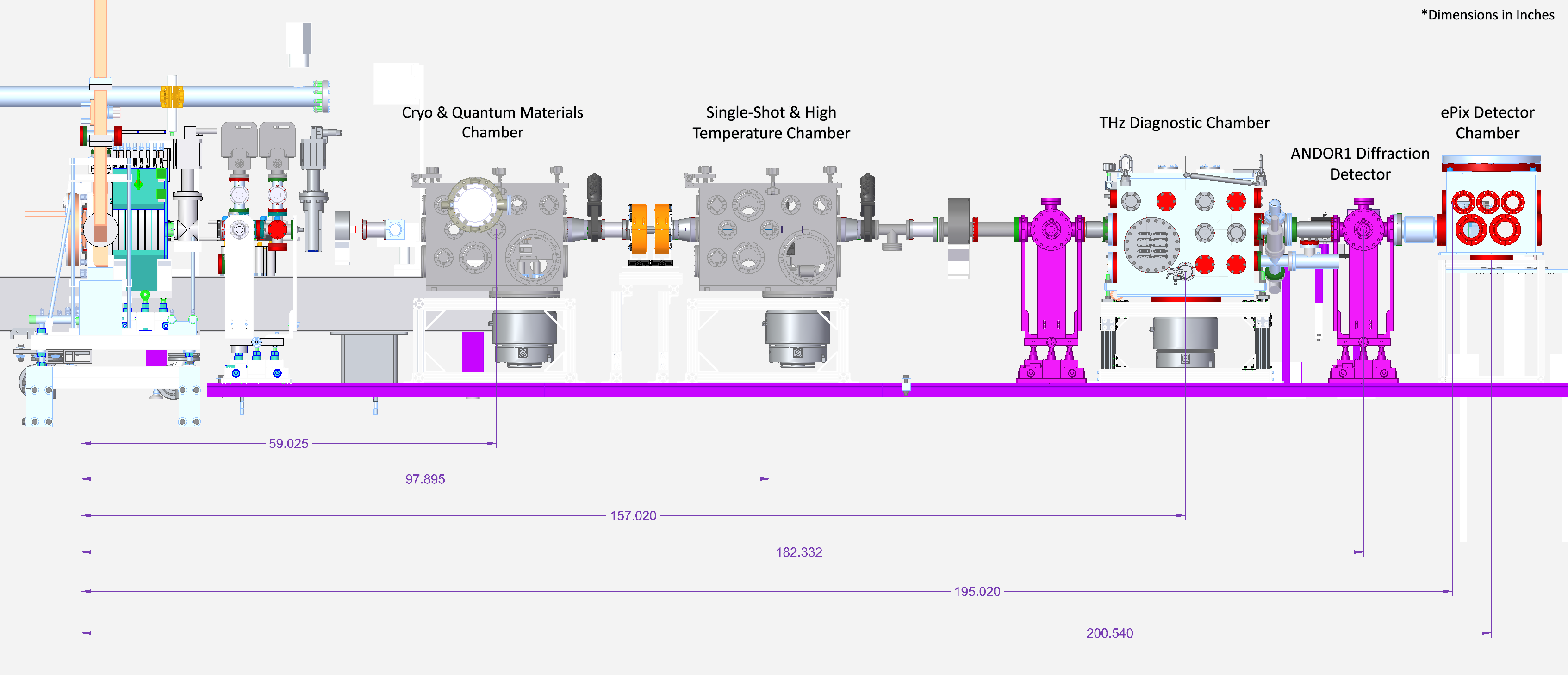
Schematic of the UED beamline in the Solid-State Material Science configuration

GUED Schematic Labeled.PNG

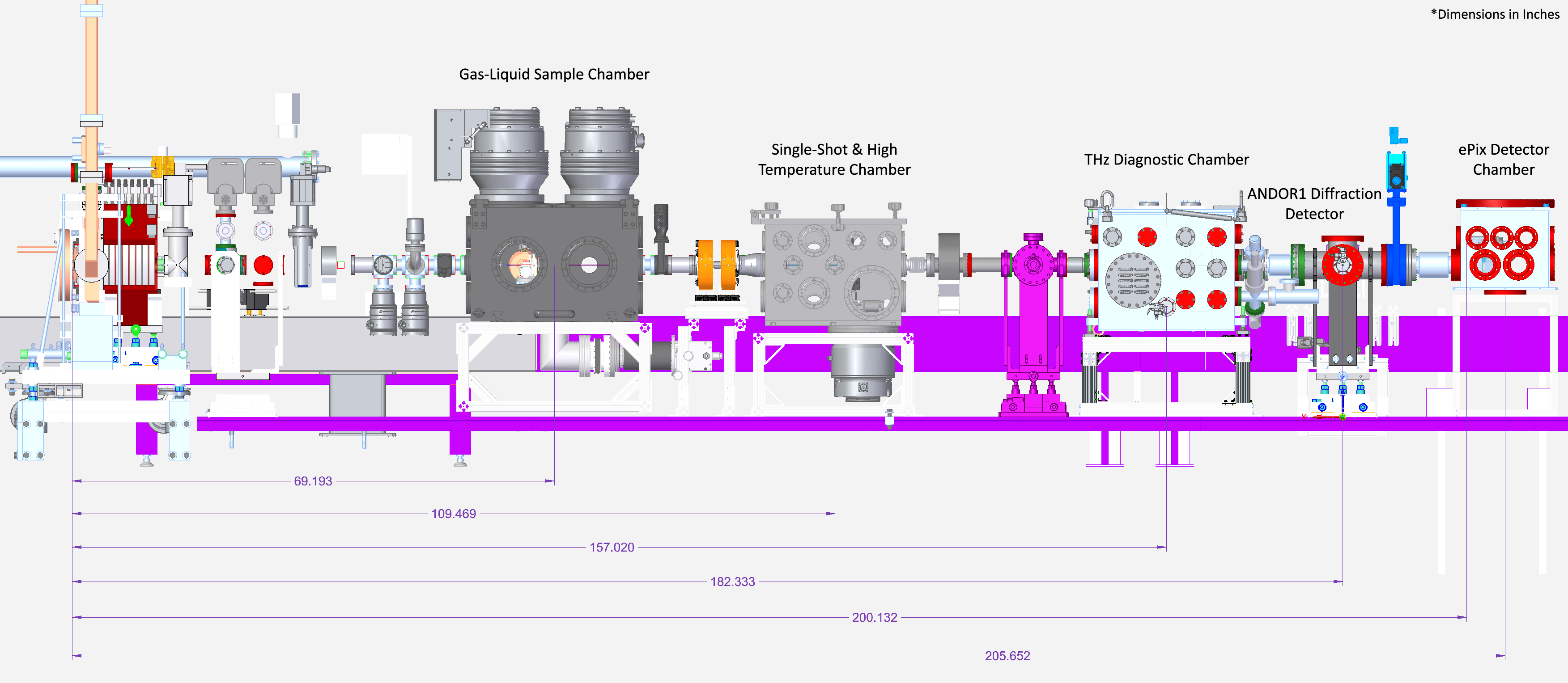
Schematic of the UED beamline in the Gas/Liquid-Phase Chemical Science configuration
Schematics of the MeV-UED beamline are shown above for both the Solid-Phase Materials Science configuration and the Gas/Liquid-Phase Chemical Science configuration. The femtosecond MeV electron bunch is generated in a S-band photocathode rf gun. The rf gun is powered by a pulse-forming-network-based modulator and a 50 MW S-band klystron. The rf amplitude and phase stability are typically 2x10⁻⁴ rms and 30 fs rms, respectively. Approximately 0.5 mJ of IR laser light is used to produce UV light to generate electrons from the copper photocathode. The UV beam illuminates the photocathode at 70 degrees angle of incidence. Immediately after photocathode a magnetic solenoid lens provides the primary electron beam focusing.
The rf photocathode gun is separated from the sample chamber environments by two differential pumping stages. The first stage holds pop-in diagnostics and an electron beam collimator. The available collimator sizes are: 100, 200 and 500 um diameter. A second magnetic solenoid lens is installed after the differential pumping sections. This allows the electron beam focus to be optimized at either the sample position or the detector position. A holey laser in-coupling mirror is installed inside the sample chamber. The sample chambers for solid-state experiments are rectangular chambers with internal dimensions: 18” x 12” x 14” and with interaction points located ~1.5 m and ~2.5 m from the photocathode. The chambers are pumped by 600 L/s turbo molecular pumps mounted at the base of each chamber.
Two detector options are available. The Andor detector is mounted 4.75 m from the photocathode, and consists of a P43 phosphor screen, which is mounted in vacuum at normal incidence to the electron beam. The phosphor screen is imaged via a flat in-vacuum mirror, downbeam of the screen, using a commercial EMCCD (Andor iXon Ultra) mounted outside vacuum. The ePIX detector is mounted directly downstream of the Andor phosphor screen and is operated in direct electron detection mode with the phosphor screen retracted.